Constructing Jupiter
Chrysler Corporation Missile Division, Warren, Michigan


#01.
[32491:
10/22/58]
Looking
into
the
tip
of
a
Jupiter
nosecone
where
you
can see the three impact fuses.
![Ed May (Left), Dept. Manager (R), 4/14/1959. [CCMD, Ed May]](index_htm_files/46929.png)

Ed May (L) & Dept. Manager
4/14/1959
Originally published: 03/24/2017
Last updated: 01/21/2018 16:36
![[60035: 6/27/1958] Re-entry vehicle, using wooden boxes to simulate actual components. Heavily instrumented for re-entry flight. [CCMD, Ed May](index_htm_files/46931.png)
#02.
[60035:
6/27/1958]
Re-entry
vehicle,
using
wooden
boxes
to
simulate
actual components. Heavily instrumented for re-entry flight.
The
following
five
photographs
are
of
Jupiter
Missile
R&D
(Research
&
Development)
Nose
Cones
built
by
CCMD
(Chrysler
Corporation
Missile
Division)
in
1959.
The
Nose
Cone
was
designed
to
deliver
on
target
a
W-
49
thermonuclear
1.45
mega
ton
bomb.
For
redundancy,
the
bomb
fuse
system
had
three
triggers:
the
first
was
a
proximity
device
set
to
detonate
the
bomb
at
a
set
altitude
burst
for
maximum
target
destruction.
Secondly,
if
that
did
not
work
a
timer
started
at
Nose
Cone
separation
from
the
Aft
Unit
would
detonate
the
bomb,
and
thirdly
if
those
two
failed
there
were
impact
triggers
set
to
fire
at
ground
contact.
The
impact
triggers can be seen on the inside tip of the Nose Cone shown in photo 32491.
The
scientists
and
engineers
at
the
Army
Ballistic
Missile
Agency
(ABMA)
in
Huntsville,
Alabama
came
up
with
an
ingenious
way
to
protect
the
aluminum
body
of
the
Nose
Cone
from
the
2000-degree
frictional
heat
of
reentry
into
the
earth’s
atmosphere.
They
coated
the
body
with
a
ceramic
material
that
ablated
away
to
throw
off
the
reentry
heat.
It
was
two
and
one
half
inches
thick
at
the
tip
of
the
Nose
Cone
and
tapered
to
one half inch at the rear of the Cone.
Photo
60035
is
a
view
looking
into
a
heavily
instrumented
Nose
Cone
for
measuring
in
flight
and
reentry
parameters
and
bomb
triggering
performance.
Some
of
the
instrument
boxes
are
wooden
mock
ups
at
this
stage of assembly.
Photos
62936,62937
and
62938
are
three
views
of
another
Nose
Cone
during
assemble
the
two
black
longitudinal
shapes
in
photo
62937
on
the
right
side
of
the
Nose
Cone
are
two
of
the
four
telemetry
antennas for transmitting measurement data to ground stations.
Note
in
the
right
side
of
photo
62938
on
a
work
stand
is
the
nozzle
of
a
Rocketdyne
Model
S-3D
150
thousand pound thrust rocket engine.

NOSE CONE
AFT
The following 18 photographs are of Jupiter Missile R&D Aft Units built by CCMD in 1958 and 1959. The Aft Unit was mounted away from and on top of the Thrust Unit. The Thrust Unit consisted of propellant tanks and the [Rocketdyne] rocket engine. The Aft Unit provided vernier adjustments for flight trajectory. Contained within the conical Aft Unit was the inertial guidance and control (G&C) instrumentation that provided guidance from launch to Nose Cone designated target. Attached to the front end of the Aft Unit was the Nose Cone. The Aft Unit and Nose Cone together are called the Body Unit. Photo 73697 is a view looking into the front of an Aft Unit sitting on a factory work stand. On the right in the photo marked Army is the Thrust Unit of a Redstone Missile also built by CCMD. For orientation, the four compartments formed by the X crossed instrument panels will be referred to as quadrants with number one at the top and clockwise to quadrant number four. The ST-90 stable platform was mounted in quadrant one floating in a stable position with respect to the earth. With a system of gyroscopes and accelerometers the ST-90 would measure deviations in three- dimensional space from the missile’s programed flight path, then provide this data to other instruments which created and provided corrections to maintain the Nose Cone on its programed course to target. The word CAUTION is marked on the aft bulkhead which with the Nose Cone attached to the front of the Aft Unit sealed the instrument compartment to atmospheric pressure. A small 500 pound thrust rocket located in the rear of the Aft Unit would be fired to move the Aft Unit away from the Thrust Unit to prevent its forward momentum from colliding with the Body Unit after Thrust Unit separation. Upon attaining ballistic flight path’s apogee the Body Unit would be oriented in the same attitude in which it had left the atmosphere. Spatial attitude control high pressure jets in the Aft Unit would be fired causing the Body Unit to tilt so that the Nose Cone would be pointed down toward the earth, at which time the Aft Unit’s Spin Rockets would be fired adding Nose Cone ballistic stability during the remainder of its flight to target. The Nose Cone would then be separated from the Aft Unit by detonating primer cord wrapped around the bolts attaching the Nose Cone to the Aft unit. The Instrument Compartment’s atmospheric pressure would push the two units apart thus ensuring the Aft Unit would not interfere with the Nose Cone. Pitot Tubes, extended during countdown, were mounted in the four cylindrical items at the outer skin of each quadrant thus providing four independent airspeed data streams to the Guidance and Control package. (see Photo 73697). Ed was working in CCMD’s Department 7262, “Electro-Mechanical Design,” during the years 1958-1959 when many of these photos were taken.![[62936: 8/12/1959] Re-entry vehicle, using wooden boxes to similate actual components. Heavily instrumented for re-entry flight. [CCMD, Ed May]](index_htm_files/46932.png)
#03.
[62936:
8/12/1959]
Re-entry
vehicle,
using
wooden
boxes
to
simulate
actual components. Heavily instrumented for re-entry flight.
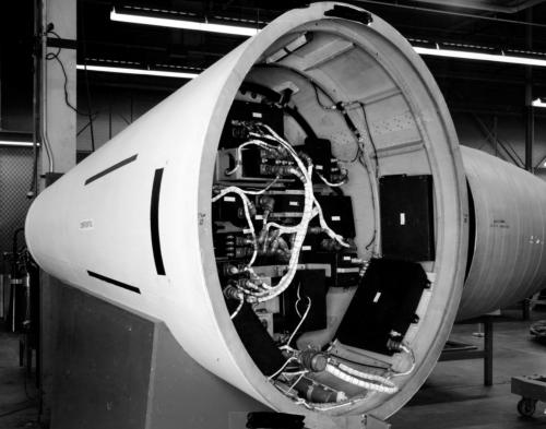
![[73697: 3/3/1960] Looking into top of Guidance Package, the Aft Unit (was mounted to main body, on top of fuel tanks), located just behind the warhead. Explosive bolts would separate re-entry vehicle. Right is shown a Redstone Missile (Tactical Missile).](index_htm_files/46933.png)
#06
[73697:
3/3/1960]
Looking
into
top
of
Guidance
Package,
the
Aft
Unit
(was
mounted
to
main
body,
on
top
of
fuel
tanks),
located
just
behind
the
warhead.
Explosive
bolts
would
separate
re-entry
vehicle.
Right
is
shown
a
Redstone Missile (Tactical Missile).
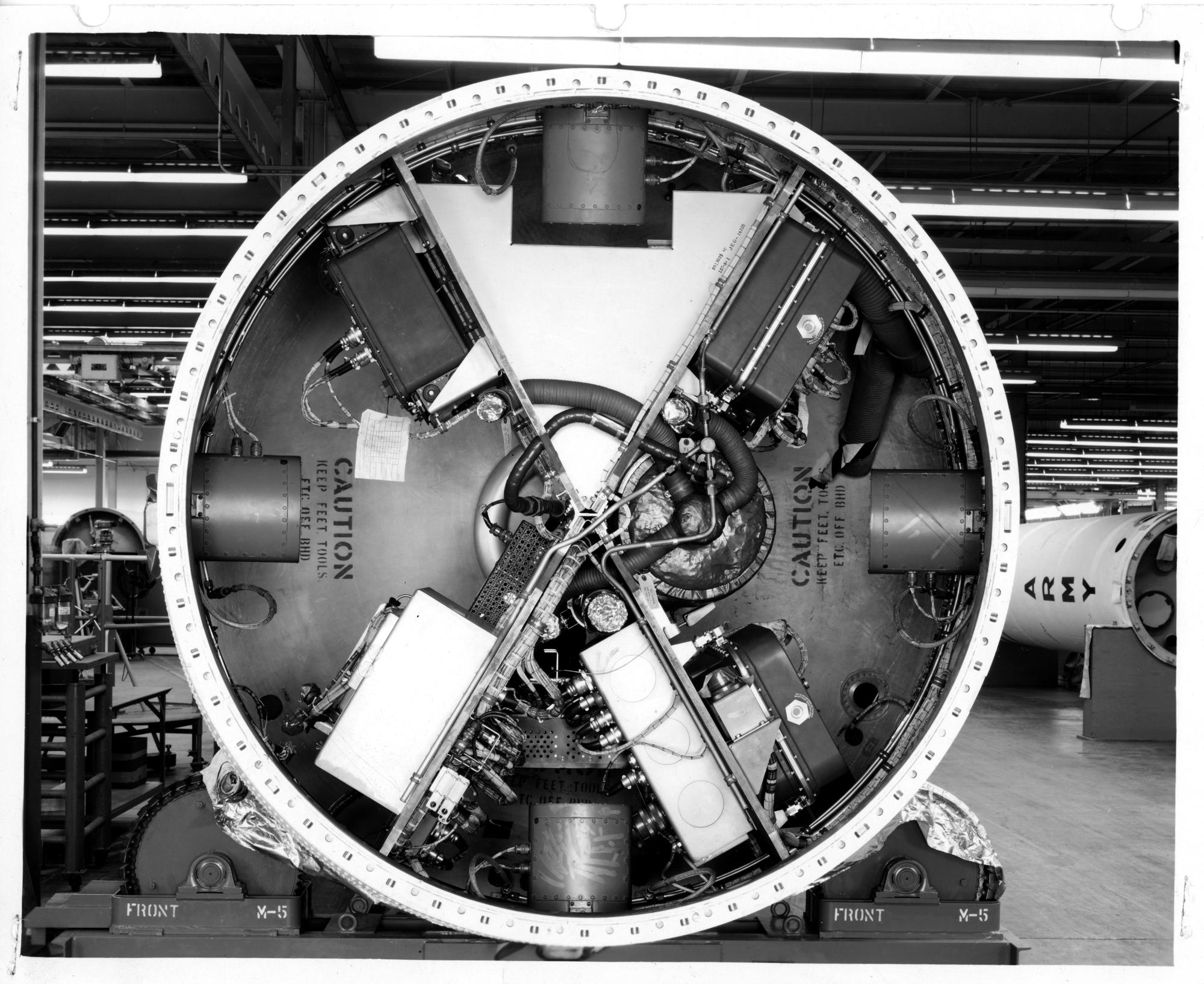
![[62938: 8/12/1959] Re-entry vehicle, using wooden boxes to similate actual components. Heavily instrumented for re-entry flight. To the right of the re-entry vehicle is an Engine Thrust Chamber. [CCMD, Ed May]](index_htm_files/46934.png)
#05.
[62938:
8/12/1959]
Re-entry
vehicle,
using
wooden
boxes
to
simulate
actual
components.
Heavily
instrumented
for
re-entry
flight.
To
the
right
of
the re-entry vehicle is an Engine Thrust Chamber.
![[62937: 8/12/1959] Re-entry vehicle, using wooden boxes to similate actual components. Heavily instrumented for re-entry flight. [CCMD, Ed May]](index_htm_files/46935.png)
#04.
[62937:
8/12/1959]
Re-entry
vehicle,
using
wooden
boxes
to
simulate
actual
components.
Heavily
instrumented
for
re-entry
flight.
The
black
“stripes”
around
the
nose
cone’s
outside
perimeter
are
telemetry
antennas.
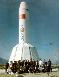
#22
[21108:
5/5/58]
Very
early
mockup
looking
into
quadrant
3
most
of
the
instruments are wooden mockups of the real items.
![[32491: 10/22/58] Looking into a real Jupiter warhead, showing impact fuse which exists in addition to a proximity fuse. There was also an electronic fuse (time into flight?) [CCMD, Ed May]](index_htm_files/46936.png)
![[21108: 5/5/58] Early mockup, parts simulated with wooden parts. Some parts were real. Wires go to dummy connectors. [CCMD, Ed May]](index_htm_files/46937.png)
![[69864: 12/7/1959] Looking into another quadrant, empty. Instrument compartment was in an "X" configuration. [CCMD, Ed May]](index_htm_files/46938.png)
#07.
[69864:
12/7/1959]
View
looking
into
quadrant
1
during
an
early
stage
of
assembly.
The
Aft
Unit
had
hatch
openings
in
each
quadrant
to
provide
excess
for
the
installation
of
the
instrumentation
and
were
covered
with
hatch
panels
at
final
assembly.
In
the
field
the
hatches
could
be
opened
for
any necessary repairs
![[69865: 12/7/1959] Looking into another quadrant. The "ball joint" device is an attachment point for the ST-90 Stabilization Platform. Sheet metal cover over the exposed vertical bracket used for cooling around stabilization platform. [CCMD, Ed May]](index_htm_files/46939.png)
#08.
[69865:
12/7/1959]
Looking
also
into
quadrant
1.
The
"ball
joint"
in
the
lower
left
corner
is
an
attachment
point
for
the
ST-90
Stabilization
Platform.
The
sheet
metal
structure
with
the
row
of
attaching
points
is
the
mounting
surface
for
the
cover
placed
over
the
ST-90
to
reduce
the
volume
to be cooled.
![[69866: 12/7/1959] Looing into quadrant where the SD-90 was mounted. Can see the cover. SD-90 is the inertial guidance stabilization platform. [CCMD, Ed May]](index_htm_files/46940.png)
#09: [69866: 12/7/1959] Close up view of the ST-90 " ball joint" attachment.
![[69867: 12/7/1959] Looking to SD-90 Quadrant. EO=Engineering Order. [CCMD, Ed May]](index_htm_files/46941.png)
#10:
[69867:
12/7/1959]
In
quadrant
1
the
white
marking
on
the
black
ST-90
mounting
ring
are
to
indicate
the
latest
engineering
change
order
(EO)
incorporated into the part.
![[70239: 12/10/1959] Showing Stable Platform Mounting Bracket, full yoke. Cooling fan blowers at top and bottom. [CCMD, Ed May]](index_htm_files/46942.png)
#11.
[70239:
12/10/1959]
Looking
straight
into
quadrant
1.
The
squared
shaped
structure
is
the
mounting
ring
for
the
ST-90.
At
the
bottom
of
the
V
is
the
300
CFM
blower
and
vents
to
circulate
cool
air
over
the
ST-90
during
flight.
![[70240: 12/10/1959] Showing Stable Platform Mounting Bracket, full yoke. Cooling fan blowers at bottom and inside. R/S Electrical Connectors covered during assembly to keep out dirt. [CCMD, Ed May]](index_htm_files/46943.png)
#12.
[70240:
12/10/1959]
Showing
Stable
Platform
Mounting
Bracket,
full
yoke.
Cooling
fan
blowers
at
bottom
and
inside.
R/S
Electrical
Connectors
covered during assembly to keep out dirt.
![[33816: 11/03/58] Instrument panels are made out of plywood. Developed honeycomb aluminum, R&D Warhead early in program. Two cutouts show 2ea antennas telemetry. [CCMD, Ed May]](index_htm_files/46944.png)
#21.
[33816:
11/03/58]
View
looking
into
quadrant
4
of
a
very
early
R&D
Aft
Unit.
Note
that
the
instrumental
panels
are
plywood.
Developed
honeycomb
aluminum,
R&D
Warhead
early
in
program.
Two
cutouts
show
2ea antennas telemetry.
#13.
[69862:
12/7/1959]
View
looking
at
the
right-side
instrument
panel
of
quadrant
2.
R&D
missiles
used
plywood
instrument
panel
but
for
weight
reduction
production
units
used
honeycombed
aluminum.
The
large
tank
held
in
place
with
the
two
metal
straps
is
the
Ln2
(liquid
nitrogen)
container
for
the
in-flight
cooling
system.
It
is
wrapped
with
insulation
held
in
place
with
duct
tape.
The
corrugated
tubing
at
the
right
side
is
for
the
exterior
pre-fight
cooling
system.
![[69862: 12/7/1959] Aft Unit Instrumentation, using honeycombed Aluminum mounting surfaces. Liquid Nitrogen in-flight cooling tank. Wrapped with insulation, wrapped with duct tape to hold in place. [CCMD, Ed May]](index_htm_files/46945.png)
![[69869: 12/7/1959] Looking into another quadrant; shows honeycomb aluminum mounting panel. Part of guidance, "Program Device," made by Ford. [CCMD, Ed May]](index_htm_files/46946.png)
#18:
[69869:
12/7/1959]
The
Flight
Programmer
is
mounted
on
the
left
instrument
panel
of
quadrant
4.
The
Ln2
fill
tube
passes
thru
the
panel
across
the
top
of
quadrant
1
thru
the
right
panel
of
quadrant
2
and
into
the Ln2 tank. At the top of the photo is the extendible pitot tube canister.
#19.
[33824:
11/03/58]
The
rear
end
of
an
Aft
Unit
sitting
on
a
factory
work
stand.
At
the
left
is
one
of
the
fiber
glass
spheres
that
held
the
high-
pressure air for the spatial attitude control system.
![[33824: 11/03/58] Looking at the bottom of the G&C package. Sphere is fiberglass for high pressure air, tested to 7500psi, Flight Tested to 3,000 psi. Spatial Directional Countrol. [CCMD, Ed May]](index_htm_files/46947.png)
![#20: [33826: 11/03/58] #19: [33824: (11/3/1958)] Thrust Unit electric cables would be connected to the five connectors shown for the transmission of signals such as rocket engine gimbling instructions for directional control, burn time and Thrust Unit separation command. At this point of assembly, the 500 pound Vernier rocket motor is not yet installed.](index_htm_files/48231.png)
![[33826: 11/03/58] Another view of the G&C package. Six electrical connectors feed propulsion unit (fuel tanks, engine). [CCMD, Ed May]](index_htm_files/46948.png)
#14.
[69863:
12/7/1959]
View
looking
at
the
left
side
instrument
panel
of
quadrant
2.
Aft
Unit
Instrumentation,
using
honeycombed
Aluminum
mounting
surfaces.
Liquid
Nitrogen
in-flight
cooling
tank.
Wrapped
with
insulation, wrapped with duct tape to hold in place.
![[69863: 12/7/1959] Aft Unit Instrumentation, using honeycombed Aluminum mounting surfaces. Liquid Nitrogen in-flight cooling tank. Wrapped with insulation, wrapped with duct tape to hold in place. [CCMD, Ed May]](index_htm_files/46949.png)
![[73698: 3/3/1960] Top of Liquid Nitrogen Cooling Tank, showing flex tubing that routes cool air to G&C package. Aluminum tubing was high pressure air feeding tank to circulate nitro for cooling. [CCMD, Ed May]](index_htm_files/46950.png)
#15.
[73698:
3/3/1960]
View
looking
at
the
top
of
the
Ln2
tank.
The
three
corrugated
tubes
are
for
routing
cooled
air
from
the
tank
into
other
quadrants.
The
Ln2
is
pumped
into
the
tank
during
countdown
through
the
small tube elbowed down into the tank.
![[69868: 12/7/1959] Black box is a 400cps Inverter, converted 28vdc DC to 400Hz AC. Unit 300cf/s cooling source was taped off. [CCMD, Ed May]](index_htm_files/46951.png)
#16.
[69868:
12/7/1959]
View
looking
into
quadrant
3
under
the
black
instrument
(which
is
an
inverter
for
converting
28-volt
DC
into
400Hz
AC)
is
the blower for the preflight cooling system.
![[69870: 12/7/1959] Looking into 4th quadrant, tubing covered with tape was part of cooling system. [CCMD, Ed May]](index_htm_files/46952.png)
#17.
[69870:
12/7/1959]
View
looking
into
quadrant
4.
The
duck
tapped
tubing is the line for filling the Ln2 tank during countdown.
GROUND CONTROL EQUIPMENT
The human interface to the Jupiter missile came through the Launch Consoles contained within the Launch Trailers. The following five photos show the Launch Trailer and their console’s initial configuration.
![[71890: 1/28/1960] Launch Control Trailer Schematic. [CCMD, Ed May]](index_htm_files/46953.png)
#23.
[71890:
1/28/1960]
Floor
plan
of
the
Electrical
Equipment
Trailer
which
was used to run periodic checkups of all missile instrumentation.

![[49597, 6/18/1959] Chrysler R&D Missile; CM AP initials: C= Chrysler M=Missile AP?=21 = Chrysler Missile 21. [CCMD, Ed May]](index_htm_files/46954.png)
#28.
[49597;
6/18/1959]
Chrysler
R&D
Missile;
CM
AP
initials:
C=
Chrysler
M=Missile
AP?=21
=
Chrysler
Missile
21
[for
reasons
of
security
to
conceal
the
number
of
the
missile
a
word
was
used
maybe
in
this
case
Able
B
for
2
and A for 1.]
![[47148: 05/06/1959] Inside Launch Trailer. [CCMD, Ed May]](index_htm_files/46955.png)
#24.
[47148:
05/06/1959]
View
looking
aft
in
the
Launch
Control
Trailer.

![[47147: 05/06/1959] Launch Console for 3 missiles. One display for each of the 3 site missiles. [CCMD, Ed May]](index_htm_files/46956.png)
#27. [47147: 05/06/1959] Close up view of the Launch Control Console.
![[43361: 03/10/1959] Juno Missile, moon shot or placing object in orbit? Cooling tower falling away on right side. [CCMD, Ed May]](index_htm_files/46957.png)
#29.
[43361:
03/10/1959]
Juno
Missile,
moon
shot
or
placing
object
in
orbit?
Cooling tower falling away on right side.
![[44647: 04/02/1959] Inside Launch Trailer. Launch Console was forward in trailer. [CCMD, Ed May]](index_htm_files/46958.png)
#25. [44647: 04/02/1959] Also looking aft in the Launch Control Trailer.
![[29998: 9/22/58] Launch Console for 3 missiles. One display for each of the 3 site missiles. [CCMD, Ed May]](index_htm_files/46959.png)
#26.
[29998:
9/22/58]
Launch
Control
Console,
one
panel
for
each
of
the
three missiles on the launch site.

Jupiter SM-78 Weapon System
I&C Team 2, Çigli AB, Turkey 1961-1962 Chrysler Corporation Missile Division


Ed May (L) & Dept. Manager
4/14/1959


NOSE CONE
The following five photographs are of Jupiter Missile R&D (Research & Development) Nose Cones built by CCMD (Chrysler Corporation Missile Division) in 1959. The Nose Cone was designed to deliver on target a W-49 thermonuclear 1.45 mega ton bomb. For redundancy, the bomb fuse system had three triggers: the first was a proximity device set to detonate the bomb at a set altitude burst for maximum target destruction. Secondly, if that did not work a timer started at Nose Cone separation from the Aft Unit would detonate the bomb, and thirdly if those two failed there were impact triggers set to fire at ground contact. The impact triggers can be seen on the inside tip of the Nose Cone shown in photo 32491. The scientists and engineers at the Army Ballistic Missile Agency (ABMA) in Huntsville, Alabama came up with an ingenious way to protect the aluminum body of the Nose Cone from the 2000-degree frictional heat of reentry into the earth’s atmosphere. They coated the body with a ceramic material that ablated away to throw off the reentry heat. It was two and one half inches thick at the tip of the Nose Cone and tapered to one half inch at the rear of the Cone. Photo 60035 is a view looking into a heavily instrumented Nose Cone for measuring in flight and reentry parameters and bomb triggering performance. Some of the instrument boxes are wooden mock ups at this stage of assembly. Photos 62936,62937 and 62938 are three views of another Nose Cone during assemble the two black longitudinal shapes in photo 62937 on the right side of the Nose Cone are two of the four telemetry antennas for transmitting measurement data to ground stations. Note in the right side of photo 62938 on a work stand is the nozzle of a Rocketdyne Model S-3D 150 thousand pound thrust rocket engine.
![[32491: 10/22/58] Looking into a real Jupiter warhead, showing impact fuse which exists in addition to a proximity fuse. There was also an electronic fuse (time into flight?) [CCMD, Ed May]](index_htm_files/47112.png)
#01.
[32491:
10/22/58]
Looking
into
the
tip
of
a
Jupiter
nosecone
where
you
can
see
the
three
impact fuses.
#02.
[60035:
6/27/1958]
Re-entry
vehicle,
using
wooden
boxes
to
simulate
actual
components.
Heavily instrumented for re-entry flight.
#03.
[62936:
8/12/1959]
Re-entry
vehicle,
using
wooden
boxes
to
simulate
actual
components.
Heavily instrumented for re-entry flight.
#04.
[62937:
8/12/1959]
Re-entry
vehicle,
using
wooden
boxes
to
simulate
actual
components.
Heavily
instrumented
for
re-entry
flight.
The
black
“stripes”
around
the
nose
cone’s
outside
perimeter are telemetry antennas.
#05.
[62938:
8/12/1959]
Re-entry
vehicle,
using
wooden
boxes
to
simulate
actual
components.
Heavily
instrumented
for
re-entry
flight.
To
the
right
of
the
re-entry
vehicle
is
an
Engine
Thrust Chamber.
AFT
The
following
18
photographs
are
of
Jupiter
Missile
R&D
Aft
Units
built
by
CCMD
in
1958
and
1959.
The
Aft
Unit
was
mounted
away
from
and
on
top
of
the
Thrust
Unit.
The
Thrust
Unit
consisted
of
propellant
tanks
and
the
[Rocketdyne]
rocket
engine.
The
Aft
Unit
provided
vernier
adjustments
for
flight
trajectory.
Contained
within
the
conical
Aft
Unit
was
the
inertial
guidance
and
control
(G&C)
instrumentation
that
provided
guidance
from
launch
to
Nose
Cone
designated
target.
Attached
to
the
front
end
of
the
Aft
Unit
was
the
Nose
Cone.
The
Aft
Unit
and
Nose
Cone
together
are
called
the
Body Unit.
Photo
73697
is
a
view
looking
into
the
front
of
an
Aft
Unit
sitting
on
a
factory
work
stand.
On
the
right
in
the
photo
marked
Army
is
the
Thrust
Unit
of
a
Redstone
Missile
also
built
by
CCMD.
For
orientation,
the
four
compartments
formed
by
the
X
crossed
instrument
panels
will
be
referred
to
as
quadrants
with
number
one
at
the
top
and
clockwise
to
quadrant number four.
The
ST-90
stable
platform
was
mounted
in
quadrant
one
floating
in
a
stable
position
with
respect
to
the
earth.
With
a
system
of
gyroscopes
and
accelerometers
the
ST-90
would
measure
deviations
in
three-dimensional
space
from
the
missile’s
programed
flight
path,
then
provide
this
data
to
other
instruments
which
created
and
provided
corrections
to
maintain the Nose Cone on its programed course to target.
The
word
CAUTION
is
marked
on
the
aft
bulkhead
which
with
the
Nose
Cone
attached
to
the
front
of
the
Aft
Unit
sealed
the
instrument compartment to atmospheric pressure.
A
small
500
pound
thrust
rocket
located
in
the
rear
of
the
Aft
Unit
would
be
fired
to
move
the
Aft
Unit
away
from
the
Thrust
Unit
to
prevent
its
forward
momentum
from
colliding
with
the
Body
Unit
after
Thrust
Unit
separation.
Upon
attaining
ballistic
flight
path’s
apogee
the
Body
Unit
would
be
oriented
in the same attitude in which it had left the atmosphere.
Spatial
attitude
control
high
pressure
jets
in
the
Aft
Unit
would
be
fired
causing
the
Body
Unit
to
tilt
so
that
the
Nose
Cone
would
be
pointed
down
toward
the
earth,
at
which
time
the
Aft
Unit’s
Spin
Rockets
would
be
fired
adding
Nose
Cone
ballistic
stability
during
the
remainder
of
its
flight
to
target.
The
Nose
Cone
would
then
be
separated
from
the
Aft
Unit
by
detonating
primer
cord
wrapped
around
the
bolts
attaching
the
Nose
Cone
to
the
Aft
unit.
The
Instrument
Compartment’s
atmospheric
pressure
would
push
the
two
units
apart
thus
ensuring the Aft Unit would not interfere with the Nose Cone.
Pitot
Tubes,
extended
during
countdown,
were
mounted
in
the
four
cylindrical
items
at
the
outer
skin
of
each
quadrant
thus
providing
four
independent
airspeed
data
streams
to
the
Guidance and Control package. (see Photo 73697).
Ed
was
working
in
CCMD’s
Department
7262,
“Electro-
Mechanical
Design,”
during
the
years
1958-1959
when
many
of
these photos were taken.
#06
[73697:
3/3/1960]
Looking
into
top
of
Guidance
Package,
the
Aft
Unit
(was
mounted
to
main
body,
on
top
of
fuel
tanks),
located
just
behind
the
warhead.
Explosive
bolts
would
separate
re-entry
vehicle.
Right
is
shown a Redstone Missile (Tactical Missile).
#07.
[69864:
12/7/1959]
View
looking
into
quadrant
1
during
an
early
stage
of
assembly.
The
Aft
Unit
had
hatch
openings
in
each
quadrant
to
provide
excess
for
the
installation
of
the
instrumentation
and
were
covered
with
hatch
panels
at
final
assembly.
In
the
field
the
hatches
could
be
opened
for
any
necessary
repairs
#08.
[69865:
12/7/1959]
Looking
also
into
quadrant
1.
The
"ball
joint"
in
the
lower
left
corner
is
an
attachment
point
for
the
ST-90
Stabilization
Platform.
The
sheet
metal
structure
with
the
row
of
attaching
points
is
the
mounting
surface
for
the
cover
placed
over
the
ST-90
to
reduce
the
volume
to
be
cooled.
#09:
[69866:
12/7/1959]
Close
up
view
of
the
ST-90 " ball joint" attachment.
#10:
[69867:
12/7/1959]
In
quadrant
1
the
white
marking
on
the
black
ST-90
mounting
ring
are
to
indicate
the
latest
engineering
change order (EO) incorporated into the part.
#11.
[70239:
12/10/1959]
Looking
straight
into
quadrant
1.
The
squared
shaped
structure
is
the
mounting
ring
for
the
ST-90.
At
the
bottom
of
the
V
is
the
300
CFM
blower
and
vents
to
circulate cool air over the ST-90 during flight.
#12.
[70240:
12/10/1959]
Showing
Stable
Platform
Mounting
Bracket,
full
yoke.
Cooling
fan
blowers
at
bottom
and
inside.
R/S
Electrical
Connectors
covered
during
assembly
to keep out dirt.
#13.
[69862:
12/7/1959]
View
looking
at
the
right-side
instrument
panel
of
quadrant
2.
R&D
missiles
used
plywood
instrument
panel
but
for
weight
reduction
production
units
used
honeycombed
aluminum.
The
large
tank
held
in
place
with
the
two
metal
straps
is
the
Ln2
(liquid
nitrogen)
container
for
the
in-flight
cooling
system.
It
is
wrapped
with
insulation
held
in
place
with
duct
tape.
The
corrugated
tubing
at
the
right
side
is
for
the
exterior
pre-fight
cooling
system.
#14.
[69863:
12/7/1959]
View
looking
at
the
left
side
instrument
panel
of
quadrant
2.
Aft
Unit
Instrumentation,
using
honeycombed
Aluminum
mounting
surfaces.
Liquid
Nitrogen
in-flight
cooling
tank.
Wrapped
with
insulation,
wrapped
with
duct
tape
to
hold
in
place.
#15.
[73698:
3/3/1960]
View
looking
at
the
top
of
the
Ln2
tank.
The
three
corrugated
tubes
are
for
routing
cooled
air
from
the
tank
into
other
quadrants.
The
Ln2
is
pumped
into
the
tank
during
countdown
through
the
small
tube elbowed down into the tank.
#16.
[69868:
12/7/1959]
View
looking
into
quadrant
3
under
the
black
instrument
(which
is
an
inverter
for
converting
28-volt
DC
into
400Hz
AC)
is
the
blower
for
the
preflight
cooling system.
#18:
[69869:
12/7/1959]
The
Flight
Programmer
is
mounted
on
the
left
instrument
panel
of
quadrant
4.
The
Ln2
fill
tube
passes
thru
the
panel
across
the
top
of
quadrant
1
thru
the
right
panel
of
quadrant
2
and
into
the
Ln2
tank.
At
the
top
of
the
photo
is
the
extendible
pitot tube canister.
#19.
[33824:
11/03/58]
The
rear
end
of
an
Aft
Unit
sitting
on
a
factory
work
stand.
At
the
left
is
one
of
the
fiber
glass
spheres
that
held
the
high-pressure
air
for
the
spatial
attitude
control system.
#17.
[69870:
12/7/1959]
View
looking
into
quadrant
4.
The
duck
tapped
tubing
is
the
line
for filling the Ln2 tank during countdown.
#22
[21108:
5/5/58]
Very
early
mockup
looking
into
quadrant
3
most
of
the
instruments
are
wooden mockups of the real items.
#21.
[33816:
11/03/58]
View
looking
into
quadrant
4
of
a
very
early
R&D
Aft
Unit.
Note
that
the
instrumental
panels
are
plywood.
Developed
honeycomb
aluminum,
R&D
Warhead
early
in
program.
Two
cutouts
show
2ea antennas telemetry.
![#20: [33826: 11/03/58] #19: [33824: (11/3/1958)] Thrust Unit electric cables would be connected to the five connectors shown for the transmission of signals such as rocket engine gimbling instructions for directional control, burn time and Thrust Unit separation command. At this point of assembly, the 500 pound Vernier rocket motor is not yet installed.](index_htm_files/48425.png)
GROUND CONTROL EQUIPMENT
The human interface to the Jupiter missile came through the Launch Consoles contained within the Launch Trailers. The following five photos show the Launch Trailer and their console’s initial configuration.
#23.
[71890:
1/28/1960]
Floor
plan
of
the
Electrical
Equipment
Trailer
which
was
used
to
run
periodic
checkups
of
all
missile
instrumentation.
![[47148: 05/06/1959] Inside Launch Trailer. [CCMD, Ed May]](index_htm_files/47114.png)
#24.
[47148:
05/06/1959]
View
looking
aft
in
the Launch Control Trailer.
#25.
[44647:
04/02/1959]
Also
looking
aft
in
the Launch Control Trailer.

#27.
[47147:
05/06/1959]
Close
up
view
of
the
Launch Control Console.
#26.
[29998:
9/22/58]
Launch
Control
Console,
one
panel
for
each
of
the
three
missiles on the launch site.
#28.
[49597;
6/18/1959]
Chrysler
R&D
Missile;
CM
AP
initials:
C=
Chrysler
M=Missile
AP?=21
=
Chrysler
Missile
21
[for
reasons
of
security
to
conceal
the
number
of
the
missile
a
word
was
used
maybe
in
this
case
Able B for 2 and A for 1.]
#29.
[43361:
03/10/1959]
Juno
Missile,
moon
shot
or
placing
object
in
orbit?
Cooling
tower
falling away on right side.
Last Updated: 01/21/2018 16:36