Working On Site
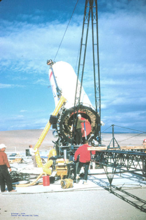
6-01: The missile, having been transported to the site, is backed up to the launch
pedestal. A launch pedestal ring is attached to the missile’s base. The back side of the
pedestal ring is hinged to the launch platform. The "A" frame routes hoisting cables
which pull the missile into an erect position. As the missile’s erection reaches a critical
point a hydraulic post known as a "snubber" is connected to the top-side of the
missile’s pedestal ring to ease the missile into its upright position. Don't want that
missile tipping over as it approaches its vertical state! Notice the gold foil surrounding
the thrust chamber? It's designed to ward off heat, etc. (GSmith, Dev Date: Oct 1961,
Slide02)
6-02: The Jupiter is about half way to its normal vertical “launch” configuration.
(GSmith, Dev Date: Oct 1961, Slide05)
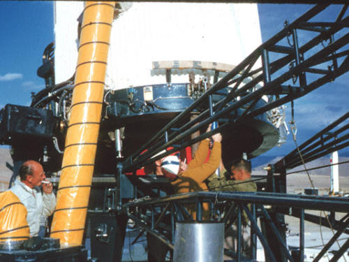
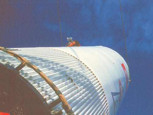
6-04: The group supervisor (Mr. Snyder (sp?)) connects the "snubber" to the missile
pedestal ring’s receptacle as the missile gets close to its vertical position. The
snubber is a hydraulic piston assembly which slowly lets the missile down to its
upright state, preventing the missile from tumbling over. (GSmith, Dev Date: Oct
1961, Slide06)
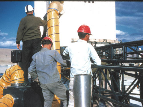
6-05: Waiting for the signal from the supervisor that the snubber is attached to the
base of the missile. That's George Smith in the white jacket gawking around, with
Kline on the right. (GSmith, Dev Date: Oct 1961 Slide08)
6-06: With the snubber attached, the missile very slowly continues on its path to
obtaining vertical configuration. (GSmith, Dev Date: Oct 1961, Slide09)
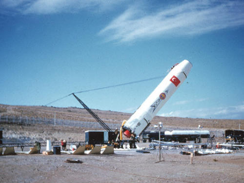
6-07: The Jupiter is almost in its vertical state at this point. You can see the cables
pulling the missile to its upright position. (GSmith, Dev Date: Oct 1961, Slide04)
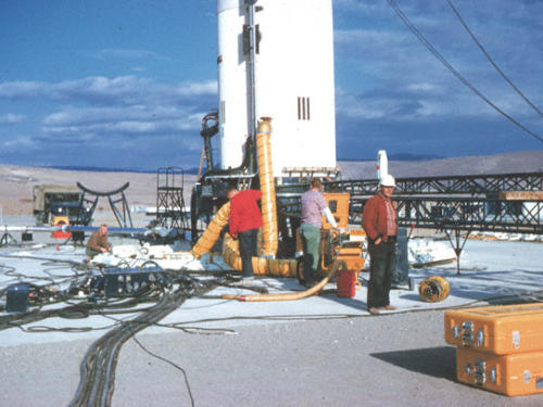
6-08: The Jupiter has reached its vertical configuration. Erection equipment can now
be disassembled and removed from the area. (GSmith, Dev Date: Oct 1961, Slide10)
6-09: Cables slack, results being checked. Jupiter is in its upright launch configuration.
(GSmith, Dev Date: Oct 1961, Slide11)
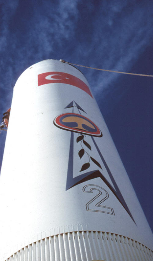
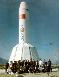
6-10: An erect Jupiter, cables slack, final operational configuration. Aimed at the sky
and ready to go...after the guidance package gets tweaked and the warhead gets
attached…which would happen after the site is turned over to the Air Force. The
“Ibrahim II” art work was provided by Ed May at the Chrysler Corporation Missile
Division plant located in Sterling Heights, Warren, Michigan, and only applied after the
Jupiter’s arrival in Turkey in part to conceal its final destination during transport from
Michigan to Turkey. (GSmith, Dev Date: Oct 1961, Slide13)
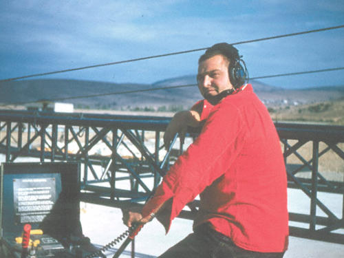
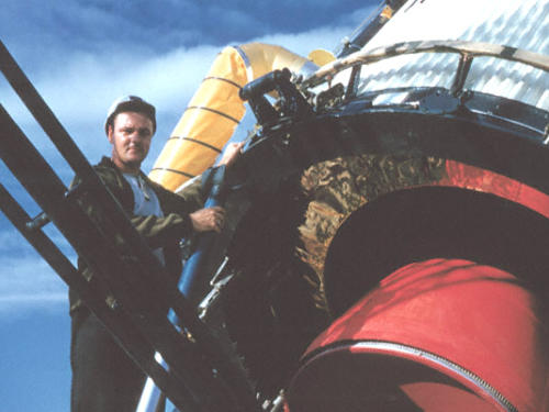
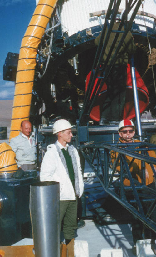
6-03: Rocketdyne, an American rocket engine design and production company, was
founded by North American Aviation in 1955. Rocketdyne supplied their engines as
propulsion units for the Jupiter missiles. A Rocketdyne tech monitors a Jupiter missile’s
engine during its erection process on LP-3. (GSmith, Dev Date: Oct 1961, Slide01)


PHOTOS - Page 6


Jupiter SM-78 Weapon System
I&C Team 2, Çigli AB, Turkey 1961-1962 Chrysler Corporation Missile Division

PHOTOS - Page 6
Working On Site
6-01: The missile, having been
transported to the site, is backed up to
the launch pedestal. A launch pedestal
ring is attached to the missile’s base. The
back side of the pedestal ring is hinged to
the launch platform. The "A" frame routes
hoisting cables which pull the missile into
an erect position. As the missile’s erection
reaches a critical point a hydraulic post
known as a "snubber" is connected to the
top-side of the missile’s pedestal ring to
ease the missile into its upright position.
Don't want that missile tipping over as it
approaches its vertical state! Notice the
gold foil surrounding the thrust chamber?
It's designed to ward off heat, etc.
(GSmith, Dev Date: Oct 1961, Slide02)
6-02: The Jupiter is about half way to its
normal vertical “launch” configuration.
(GSmith, Dev Date: Oct 1961, Slide05)
6-04: The group supervisor (Mr. Snyder
(sp?)) connects the "snubber" to the
missile pedestal ring’s receptacle as the
missile gets close to its vertical position.
The snubber is a hydraulic piston
assembly which slowly lets the missile
down to its upright state, preventing the
missile from tumbling over. (GSmith, Dev
Date: Oct 1961, Slide06)
6-05: Waiting for the signal from the
supervisor that the snubber is attached
to the base of the missile. That's George
Smith in the white jacket gawking around,
with Kline on the right. (GSmith, Dev Date:
Oct 1961 Slide08)
6-06: With the snubber attached, the
missile very slowly continues on its path
to obtaining vertical configuration.
(GSmith, Dev Date: Oct 1961, Slide09)
6-07: The Jupiter is almost in its vertical
state at this point. You can see the cables
pulling the missile to its upright position.
(GSmith, Dev Date: Oct 1961, Slide04)
6-08: The Jupiter has reached its vertical
configuration. Erection equipment can
now be disassembled and removed from
the area. (GSmith, Dev Date: Oct 1961,
Slide10)
6-09: Cables slack, results being checked.
Jupiter is in its upright launch
configuration. (GSmith, Dev Date: Oct
1961, Slide11)
6-10: An erect Jupiter, cables slack, final
operational configuration. Aimed at the
sky and ready to go...after the guidance
package gets tweaked and the warhead
gets attached…which would happen after
the site is turned over to the Air Force.
The “Ibrahim II” art work was provided by
Ed May at the Chrysler Corporation
Missile Division plant located in Sterling
Heights, Warren, Michigan, and only
applied after the Jupiter’s arrival in Turkey
in part to conceal its final destination
during transport from Michigan to
Turkey. (GSmith, Dev Date: Oct 1961,
Slide13)
6-03: Rocketdyne, an American rocket
engine design and production company,
was founded by North American Aviation
in 1955. Rocketdyne supplied their
engines as propulsion units for the
Jupiter missiles. A Rocketdyne tech
monitors a Jupiter missile’s engine during
its erection process on LP-3. (GSmith, Dev
Date: Oct 1961, Slide01)